Tag: Voltage Regulator

Understanding The Working of a Voltage Regulator

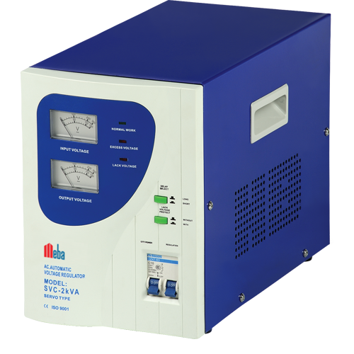
A voltage regulator generates a set output voltage of a predefined magnitude that stays constant regardless of modifications to its input voltage or load conditions. Voltage regulator comes in two flavors: switching and linear.

A power MOSFET or BJT switch receives a switched voltage from a switching regulator, which is then altered from the DC input voltage. To maintain a consistent output voltage independent of variations in input voltage or load current, the output voltage is supplied back to a circuit that regulates the power switches on and off timings.

Which switching regulator topologies are there?
Buck (step-down), boost (step-up), and buck-boost (step-up/step-down) are the three most popular topologies. Additional topologies include the flyback, SEPIC, Cuk, push-pull, forward, full-bridge, and half-bridge topologies.

What impact does switching frequency have on regulator design?
The automatic voltage regulator may employ fewer inductors and capacitors because of the higher switching frequency. Additionally, it causes greater switching losses and circuit noise.

What losses does the switching regulator produce?
Losses arise from the power used to switch on and off the MOSFET, which is coupled to the gate driver of the MOSFET. Additionally, MOSFET power losses happen because switching between the conduction and non-conduction states requires a certain amount of time. The energy required to charge and discharge the MOSFET gate’s capacitance between the threshold voltage and gate voltage results in losses as well.

What applications do switching and linear regulators often serve?
Since the linear regulator’s power dissipation is directly proportional to its output current for a given input and output voltage, its average efficiency might be as low as 50%. A switching regulator may attain efficiency in the 90% range when using the best parts. With the same output voltage and current demands, a switching regulator produces noise that is significantly higher than a linear regulator. Compared to a linear regulator, the switching regulator frequently offers better current load-driving capabilities.

What critical design specifications apply to an integrated circuit voltage regulator?
Some of the basic characteristics include output current, input voltage, and voltage. The linear automatic voltage regulators dropout voltage, PSRR, and output noise are crucial variables.

Understanding Automatic Voltage Regulators: Ensuring Stable Power Supply

Automatic voltage regulators (AVRs) are electrical devices that are designed to maintain a consistent output voltage despite variations in the input voltage. They serve as an important line of defense between the power source and the sensitive equipment by constantly monitoring and changing voltage levels to ensure they remain below permissible limits.

AVR functionality:

An Automatic Voltage Regulator’s principal duty is to regulate and stabilize the output voltage within a predetermined range. AVRs do this by taking the following steps:

  • Voltage Sensing: The AVR continually checks the power source’s input voltage. It detects any fluctuations, such as overvoltages (excessive voltage) or under voltages (inadequate voltage).
  • Voltage Comparison: The measured voltage is compared to a reference value that has been pre-set. The AVR begins correction actions if the input voltage deviates from the required level.
  • Voltage Regulation: Using several approaches, the AVR changes the output voltage based on the comparison. The most typical approach includes the use of transformers and electrical circuits to adjust the voltage as needed.
  • Automatic voltage regulators continuously monitor the output voltage and alter it in real-time to compensate for variations in the input voltage. This dynamic control guarantees that linked devices receive a consistent and stable supply of power.

The significance of AVRs:

  • Voltage Fluctuations Protection: AVRs protect sensitive electronic devices against voltage fluctuations, such as computers, medical equipment, industrial machinery, and telecommunications systems. They avoid damage, premature wear, and data loss by keeping a constant voltage supply.
  • Performance and dependability of equipment: AVRs’ stable voltage levels improve the performance and lifetime of electrical devices. Consistent voltage decreases the possibility of short circuits and assures efficient operation.
  • AVRs assist in saving money by avoiding the need for frequent repairs or replacements due to voltage-related concerns. AVRs reduce the risk of downtime and related productivity losses by ensuring a constant voltage supply.

Voltage Adaptation: When the power supply and the equipment run at various voltage levels, a voltage regulator can be used to alter and adapt the voltage to meet the specific needs, assuring compatibility and safe operation.

Understanding Voltage Regulators: The Key to Stable and Reliable Power Supply

Understanding Voltage Regulators: The Key to Stable and Reliable Power Supply

A voltage regulator is an electronic circuit that is designed to automatically maintain a constant output voltage level regardless of any changes to the input voltage or load conditions. It is used to provide a stable and reliable source of power to various electrical devices and systems.

Voltage regulators can be found in a wide range of applications, from simple electronic gadgets to complex industrial systems. They are used in power supplies, motor controllers, battery chargers, and many other devices that require a stable and consistent voltage output.

Meba Electrical AC Voltage Stabilizer SVC-P2KVA

There are several types of voltage regulators, but the most common types are linear regulators and switching regulators.

Linear regulators are the simplest and most basic type of voltage regulators. They work by adjusting the resistance of a pass transistor to regulate the output voltage. Linear regulators are easy to use and require few external components, making them ideal for low-power applications. Switching regulators are more complex than linear regulators, but they offer higher efficiency and better performance. They use a switching element, such as a transistor or a diode, to rapidly switch the input voltage on and off, and then use a filter to smooth out the output voltage.

There are many factors to consider when selecting automatic voltage regulators, such as input voltage range, output voltage range, load current, and efficiency. Other factors such as temperature range, packaging, and cost should also be taken into account.

One important consideration when using a voltage regulator is to ensure that the input voltage is within the specified range of the regulator. Input voltages that are too high can cause the regulator to overheat, while input voltages that are too low can cause the regulator to operate in dropout mode, resulting in an unstable output voltage.

Another important consideration is the load current. A voltage regulator must be able to handle the maximum load current that will be drawn from it without overheating or causing the output voltage to drop. When selecting an automatic voltage regulator, it is important to consider the specific requirements of the application to ensure that the regulator can provide the necessary performance and reliability.

Follow us on Facebook

Get to Know About the Voltage Regulator

Get to Know About the Voltage Regulator

All electrical equipment is programmed to operate at the preset voltage and current levels. The voltage supply is fixed and, ideally, constant for the device to work properly, whereas current consumption is dynamic and dependent on the device load. The ideal voltage required by the gadget must be maintained by a voltage regulator. Voltage regulators are present in your laptop, wall charger, and coffee maker.

The idea of a voltage regulator and its many forms will be examined in further detail in this blog, along with the common voltage regulator ICs and their typical uses.

A voltage regulator is what?

An electronic device’s power supply unit transforms incoming power into the necessary voltage/current characteristics and type. A voltage regulator is a part of the power supply unit that makes sure the voltage supply is consistent and steady under all operational circumstances. During power outages and changes in load, it controls voltage. Both AC and DC voltages can be regulated using it.

Typically, an automatic voltage regulator receives a larger input voltage and outputs a lower, steadier value. Their secondary function is to shield the electronic circuit from voltage spikes that can harm or fry them.

Many voltage regulator types

Integral circuits are frequently employed as voltage regulators in low-voltage electronic devices. Power distribution centers employ more advanced and mechanically big voltage regulators to maintain regulated 110 V (US home standards) voltage regardless of consumer needs in the neighborhood. These centers provide AC power to residential and industrial users.

Meba AC Voltage Stabilizer TND-2KVA

Automatic voltage regulators can be found in integrated circuits, electromechanical devices, or solid-state automatic regulators, depending on the physical design. Linear and switching regulators are the two most popular subcategories of active voltage regulators. Simple transistor-based linear regulators are frequently manufactured as integrated circuits (ICs). Differential amplifiers are used by their internal circuitry to regulate output voltage in comparison to a reference voltage. The output of linear voltage regulators can be fixed or adjustable. Typically, they require an input current equal to the output current.

High-frequency switching regulators change the output voltage’s duty cycle by turning a series device on and off. They frequently use buck, boost, and buck-boost topologies.

Follow us on Facebook

Understanding the Working of a Voltage Regulator

Understanding the Working of a Voltage Regulator

A fixed output voltage of a preset magnitude is generated by a voltage Regulator that remains constant irrespective of changes to its load conditions or input voltage. Switching and linear are two types of voltage regulators.

An active pass device controlled by a high gain differential amplifier is employed by a linear regulator. With a precise reference voltage, it compares the output voltage, and to maintain a constant output voltage, it adjusts the pass device.

voltage Regulator

To a circuit that controls the power switch on and off times, the filtered power switch output voltage is fed back so that regardless of load current or input voltage changes, the output voltage remains constant.

Switching regulator associated losses

As a result of the power needed to turn the MOSFET on and off, Losses occur which are associated with the MOSFET’s gate driver. Also as it takes a finite time to switch to/from the conduction to no conduction states, MOSFET power losses occur. Due to the energy needed to discharge and charge the capacitance of the MOSFET gate between the gate voltage and threshold voltage, Losses occur. The Power Regulator is also useful.

Design specifications crucial for IC of a voltage regulator

The output current, output voltage, and input voltage are the basic parameters. Other parameters may be important based on the application, such as efficiency, load transient response, output ripple voltage, and output noise. Important parameters for the linear regulator are output noise, power supply rejection ratio, and dropout voltage. With a precise reference voltage, it compares the output voltage, and to maintain a constant output voltage, it adjusts the pass device.

voltage Regulator

Switching and linear regulators applications

The linear regulator’s power dissipation for a given output and input voltage is directly proportional to its output current. So, typical efficiencies can be 50% or even lower. Efficiencies in the 90% range can be achieved by using the optimum components like a switching regulator. However, as compared to a switching regulator with the same output voltage and current requirements, the noise output from a linear regulator is much lower. Typically, higher current loads can be driven by the Automatic Voltage Regulator than a linear regulator. Follow us on Twitter

Learn the Limitations of Voltage Regulator

Learn the Limitations of Voltage Regulator

There are maximum integrated IC’s that need a constant voltage with which they could operate. They have their voltage regulator no matter whether it is a simple Logic Gate or a complex microprocessor. The most common operating voltages are 5V, 12V, and 3.3V.To act as a voltage source we have batteries and DC Adaptors as the maximum time to our circuit design they cannot be directly connected since the voltage from them is not regulated.

A voltage regulator is a beefed-up emitter follower. A transistor a stable reference is connected that spits out a constant voltage, dropping the remaining.

Meba UPS Power Supply SVC-O1000VA

They even consist of a built-in error amplifier, which samples the output voltage (again through a divider), then with the reference voltage it is compared, the difference is calculated, and accordingly drives the output transistor. From voltage divider, this is far different, which through just a magnitude smaller faithfully replicates the input signal.

Meba LCD Voltage Regulator SVC-C 500VA

Limitations of Voltage Regulator

The simplicity of linear regulators is the biggest advantage; nothing else is needed.

However, they are available with their own set of limitations.

The working of the linear voltage regulator is associated with a variable resistor that provides feedback, dropping any unneeded voltage. Into heat this wasted energy is converted, making the power regulator hot and inefficient at high currents.

For example, a power loss of (12V – 5V)*1A is seen with a 5V regulator with a 12V input running at 1A, which is 7W. This says there is a lot of wasted energy, and the efficiency is only 58%.

So, at differentials of high input-output voltage or high currents, regulators have pathetic energy efficiency.

With the use of more than one regulator in series with decreasing output voltages (up to the desired voltage value) the input-output differential voltage problem can be overcome so that in steps the voltage is dropped. The overall power dissipation is equivalent to having one automatic voltage regulator across all the devices the heat load is spread out along with decreasing overall operating temperature. By using a switching supply the power and efficiency limitations can be overcome, but the choice is application dependent.